Robust 4-way radiometer that requires little maintenance


Overview
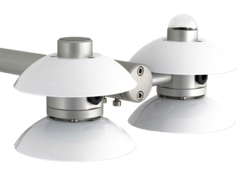
The NR01, manufactured by Hukseflux, is a research-grade net radiometer that measures the energy balance between incoming short-wave and long-wave infrared radiation versus surface-reflected short-wave and outgoing long-wave infrared radiation. Our dataloggers measure the NR01's output and control its internal heater. This net radiometer offers a professional solution for scientific-grade energy balance studies.
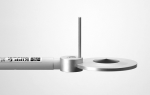
Note: NR01 radiometers with a serial number less than 2313 used the pn #21271 fitting. NR01 radiometers with a serial number greater than 2312 do not need the pn #21271 fitting.
Read MoreBenefits and Features
- Internal RTD provides temperature compensation of measurements
- Research-grade performance
- Internal 1-W heater reduces formation of dew and melts frost
- Separate outputs of short-wave and long-wave infrared radiation for better accuracy and more thorough quality assurance
- Robust—only requiring limited maintenance
Images

Related Products
Technical Description
The NR01 consists of a pyranometer and pyrgeometer pair that faces upward and a complementary pair that faces downward. The pyranometers and pyrgeometers measure short-wave and far infrared radiation, respectively.
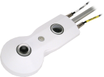
The NR01 includes an on-board RTD to measure the radiometer’s internal temperature and a 1-W heater that minimizes the formation of dew and melts frost. To reduce current drain, a relay is typically used to turn on the heater only when the solar radiation is less than 20 W/m2.
Campbell Scientific's CR3000 and CR5000 dataloggers are ideal for measuring this radiometer. A CR1000 can also be used, but a 4WPB100 module is required to measure the internal RTD.
Specifications
| Sensor | Hukseflux’s SR01 ISO-class, thermopile pyranometers, IR01 pyrgeometers, PT100 RTD |
| Measurement Description | Measures incoming and outgoing short-wave and long-wave radiation |
| Response Time | 18 s |
| Sensitivity | 10 to 40 μV W-1 m2 |
| Expected Output Range | -0.1 to +50 mV |
| Expected Accuracy for Daily Totals | ±10% |
| Heater | 90 ohm, 1.6 W (at 12 Vdc) |
| Operating Temperature Range | -40° to +80°C |
| Heater Current Drain | ~140 mA |
| Dimensions | 26.3 x 11.3 x 12.1 cm (10.4 x 4.4 x 4.8 in.) |
| Weight |
|
Pyranometer |
|
| Spectral Range | 305 to 2800 nm |
Pyrgeometer |
|
| Spectral Range | 4500 to 50,000 nm |
Compatibility
Please note: The following shows notable compatibility information. It is not a comprehensive list of all compatible products.
Dataloggers
| Product | Compatible | Note |
|---|---|---|
| CR1000 (retired) | A 4WPB100 PRT Bridge Module is required to measure the internal RTD. | |
| CR1000X | A 4WPB100 PRT Bridge Module is required to measure the internal RTD. | |
| CR3000 | ||
| CR6 | ||
| CR800 (retired) | ||
| CR850 (retired) |
Mounting Equipment
| Product | Compatible | Note |
|---|---|---|
| NR Sensor Mount |
Additional Compatibility Information
Mounting
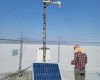
To avoid shading or reflections and to promote spatial averaging, the NR01 should be mounted at least 1.5 m above the ground or crop canopy and away from all obstructions or reflective surfaces that might adversely affect the measurement. Campbell Scientific recommends mounting the NR01 to a CM300-series mounting pole at least 25 feet away from other mounting structures. The NR01 is attached to the CM300-series mounting pole via a CM204 or CM206 crossarm.
Resources and Links
Product Brochures
Manuals
FAQs for
Number of FAQs related to NR01: 12
Expand AllCollapse All
-
Campbell Scientific recommends that the sensor be mounted to a separate vertical pipe at least 25 ft from any other mounting structures.
-
It is possible that an older version of Short Cut is being used. Download the latest version of Short Cut.
For programming assistance, consult the NR01-L instruction manual. For additional assistance, contact Campbell Scientific.
-
Shading and reflection are important aspects to consider. The sensor should have a clear view of the upward hemisphere of the sky. To avoid shading effects and to promote spatial averaging, the sensor should be mounted at least 1.5 m above the ground surface.
-
As of June 2013, all of our current and retired net radiation sensors can be mounted using this kit. These include:
- Current sensors: CNR4-L, NR-LITE2-L, and NR01-L
- Retired sensors: CNR1, CNR1-L, CNR2-L, NR-LITE-L, and Q7.1-L
-
Mount the net radiometer so that no shadow will be cast on it at any time of day from obstructions such as trees, buildings, the mast, or the structure on which it is mounted.
Campbell Scientific recommends installing a net radiometer in an open area, away from the main weather station structure on a separate vertical mast. If it is necessary to install this sensor on the main tall tower (30 ft or taller), the sensor should be installed at the top of the tower. In the northern hemisphere, the sensor should be facing south. In the southern hemisphere, the sensor should be facing north. If the tower uses a solar power system (that is, solar panels), ensure that the solar panels are installed away from the main tower.
-
Only one 4WPB100 is needed to measure the internal PRT in the radiometer.
-
The CR1000 requires a 4WPB100 to measure the internal PRT. (Data loggers such as the CR3000 and CR5000 have the necessary PRT bridge module built in to measure the PRT.) Note that the CNR4-L also includes an internal thermistor, which can be directly measured by the CR1000. Because of this, when using a CR1000, Campbell Scientific typically recommends monitoring the internal temperature of the CNR4-L using its internal thermistor instead of the PRT.
-
Because of the loss of IR radiation, nearly all thermopile instruments typically have a negative offset. This offset is most easily visible at night-time, when a small negative value is read instead of zero. This same offset is present during the daytime, but it is not as visible because of the large solar signal.
Another common issue involves leveling an instrument. Leveling a thermopile instrument can cause errors in the direct beam component because the cosine response is not correct. These errors are more notable when the sun is close to the horizon because the angle is so shallow.
-
Not every sensor has different cable termination options. The options available for a particular sensor can be checked by looking in two places in the Ordering information area of the sensor product page:
- Model number
- Cable Termination Options list
If a sensor is offered in an –ET, –ETM, –LC, –LQ, or –QD version, that option’s availability is reflected in the sensor model number. For example, the 034B is offered as the 034B-ET, 034B-ETM, 034B-LC, 034B-LQ, and 034B-QD.
All of the other cable termination options, if available, are listed on the Ordering information area of the sensor product page under “Cable Termination Options.” For example, the 034B-L Wind Set is offered with the –CWS, –PT, and –PW options, as shown in the Ordering information area of the 034B-L product page.
Note: As newer products are added to our inventory, typically, we will list multiple cable termination options under a single sensor model rather than creating multiple model numbers. For example, the HC2S3-L has a –C cable termination option for connecting it to a CS110 instead of offering an HC2S3-LC model.
Case Studies
The Utah Geological Survey, supported by the Utah Division of Water Rights, has constructed a......read more
Privacy Policy Update
We've updated our privacy policy. Learn More
Cookie Consent
Update your cookie preferences. Update Cookie Preferences