7 Steps to Determine if Your Solar-Charged Power Supply Has a Problem
by Jason Ritter | Updated: 11/24/2015 | Comments: 5
Blog Topics
Area / Application


Product Category


Corporate / News
Search the Blog
Subscribe to the Blog
Get an email when a new article is posted. Choose the topics that interest you most.
Suggest an Article
Is there a topic you would like to learn more about? Let us know.
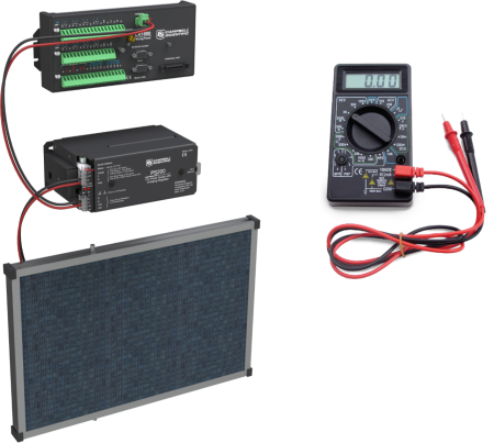
Are you having communication problems or seeing readings you don't trust? Is it possible your solar-charged power supply is the cause? How can you find out for sure?
As we mentioned in the “6 Steps to Determine if Your Data Logger Needs Repairing” blog article, many data acquisition system failures are caused by problems with the power supply. These may include issues with batteries, charge regulators, or charging sources. In this article, we’ll look at seven steps to help you find out if your solar-charged power supply has a problem.
Before we get started, you will need to have these tools handy:
- Good digital multimeter (DMM)
- Small (2.5 mm) flat-bladed screwdriver
- Pair of wire strippers
Most of the steps outlined here involve direct current (dc) or voltage measurements on different parts of your power system. To measure the dc voltage, set your DMM to the 20 Vdc range with the red probe firmly in the mAVΩ socket and the black probe firmly in the COM socket. During testing, you will touch the red probe to one of the following: the terminal screw labeled 12V, +, or the bare end of a red wire. In contrast, you will touch the black probe to one of these: the terminal screw labeled G, -, or the bare end of a black wire.
#1 - Test the data logger POWER IN

You can check whether the data logger is getting power from the power supply by following these steps:
- Measure the voltage on the power input terminals of the data logger. Most Campbell Scientific data loggers have a green plug that connects to a socket labeled POWER IN.
- If your data logger does not have the two-pin connector, you will need to trace the wires from the battery to the data logger and make the measurements there.
- Touch the black probe to the terminal screw labeled G or Battery -.
- Touch the red probe to the terminal screw labeled 12V or Battery +.
- If the voltage reads greater than 11 V, the test is successful, and your data logger is receiving enough power.
- If the voltage reads less than 11 V, there is likely an issue with your power supply. Work through the following steps to find out where it is failing.
#2 - Ensure the power supply is turned on
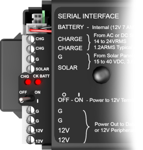
You might be surprised how common it is for someone to turn off the power to a data logger for some reason and then forget to turn it back on later. (For more information on this subject, read the “Troubleshooting Best Practices for Data Acquisition Systems” blog article.)
- If the power switch is in the Off position, move it to the On position, and repeat step #1.
- If the power switch is already in the On position, proceed to step #3.
#3 - Measure the voltage on the power supply
If you look at your power supply, do you see multiple terminals labeled 12V and G? Just pick one of each terminal type to use.
Measure the voltage between the 12 volt and ground terminals on your power supply. If you measure more than 11 V on the power regulator, but less than 11 V on the data logger, check the wires that connect them.
- If you find a loose wire, turn off the power before reconnecting it.
- If you find good electrical connections on the wires, move on to step #4.
#4 - Check the voltage on the battery
At this step in the process, your measurements have been less than 11 V for both the data logger and the power supply. The next step is to test the battery voltage with the black probe on the negative (-) terminal and the red probe on the positive (+) terminal.
- If the voltage reads greater than 11 V, the battery is OK, but the power supply needs to be returned for repair. Contact Campbell Scientific for a Return Material Authorization (RMA).
- If the voltage reads less than 11 V, disconnect the battery.
#5 - Without a battery attached, check the voltage on the power supply
With the battery disconnected, you can recheck the voltage on the power supply using step #3 as a guide.
- If the voltage between 12V and G reads 13 to 14 V, the battery needs to be replaced.
Now check the voltage on the two charge terminals of the power supply. These are both labeled CHG, but it doesn't matter which color probe you put on which terminal.
- If the voltage on the charge terminals reads more than 17 V, the power supply needs to be returned for repair. Contact Campbell Scientific for a Return Material Authorization (RMA).
#6 - Measure the voltage on the solar panel

Now it's time to disconnect the solar panel from the power supply. You can measure the panel’s voltage by touching the probes to the ends of the panel’s bare wires. Be sure to do this test during the day at a time when the solar panel is not covered or in the shade. With the red probe touching the red wire, and the black probe touching the black wire, measure the voltage.
- If the voltage on the solar panel reads less than 17 V when the panel is in full sun, the solar panel needs to be replaced.
#7 - Test the current of the solar panel
For this last step, set your DMM to measure amps so that you can measure the current coming from the solar panel.
Tip: To avoid sparking, it's good practice to temporarily cover the solar panel with a cloth or something similar.
Measure the current by following these steps:
- Move the red lead on the DMM to the 10ADC socket, and set the range to 10 A.
- Connect the red probe to the positive (red) lead on the solar panel.
- Connect the black probe to the negative (black) lead on the solar panel.
- With the probes connected, remove the covering from the solar panel, and expose the solar panel to sunlight. The table below shows the expected maximum output current for different sizes of solar panels.
Solar Panel Output Maximum Output Current (shorted) 10 W
0.7 A
20 W
1.4 A
50 W
3.3 A
90 W
5.6 A
Depending on the time of day and weather, your measurement will probably be lower than the maximum listed, but it should be close to the value that is appropriate for the size of your solar panel.
- When the panel is in the sun, if the measurement of the current from the solar panel is close to the maximum output current, but the voltage on the 12V and G terminals from step #5 is less than 13 to 14 V, then the power supply should be returned for repair. Contact Campbell Scientific for a Return Material Authorization (RMA).
- If the measurement of the current from the solar panel isn't realistic, either the solar panel or the wires connecting the solar panel to the power supply may be damaged.
Testing Data Loggers with Built-in Power Supplies
Some Campbell Scientific data loggers have their power supply built into a rechargeable battery base. For this type of data logger, before you can perform steps #5 and #6, you will need to disconnect the battery by separating the data logger module from the base. (For more details, see your data logger manual.)
In Summary
To find a power supply problem, we start at the data logger and test each part of the system back to the charging source. After you perform these steps, contact Campbell Scientific if you find any of the conditions outlined below:
| Condition | Cause |
|
The voltage from the power supply is less than 11 V with the battery attached, but the voltage increases to 13 to 14 V when the battery is disconnected. |
The battery needs to be replaced. |
|
The battery voltage is more than 11 V, but the voltage from the power supply is less than 11 V. |
The power supply needs to be repaired. |
|
The voltage on the charge terminals is more than 17 V, but the voltage between 12V and G on the power supply is outside the range of 13 to 14 V. |
The power supply needs to be repaired. |
|
The current output from the solar panel is realistic, but the voltage between 12V and G on the power supply is outside the range of 13 to 14 V. |
The power supply needs to be repaired. |
|
When the solar panel is in the sun, the solar panel voltage is considerably less than 17 V. |
The solar panel is defective or damaged. |
|
When the solar panel is in the sun, the solar panel current is not close to its maximum output current. |
The solar panel is defective or damaged. |
If your solar-charged power supply has a condition that hasn’t been covered in this article, or if you have a question, post your comment below.


About the Author
 Jason Ritter was a Senior Support and Implementation Specialist at Campbell Scientific, Inc. He worked with customers to help them make the best measurement possible. Jason was a longtime fan of Campbell Scientific, having been a customer for ten years before joining the company as an application specialist. He also held the positions of soil scientist, soils product manager, soils market manager, and product group manager.
Comments
djtire | 11/24/2015 at 12:23 PM
It is also possible that a sensor that is using the 12V or SW12 may be causing the problem. If battery is good, the charging source is good, and the charge controller is good, but the system seems to be having power issues it could be a sensor or sensor cable issue.
We recently had a client who's datalogger would power up, appear fine for about a short period and then disconnect from the PC he was using to communicate with it. After several times of rebooting the power and trying to maintain communication without success, he call us. We went through the process described above and found everything was fine. Then we started to disconnect sensors that were using the 12V terminal, one by one. Sure enough, one of the sensor was the culprit. With the sensor disconnected everything returned to normal.
Notso | 11/24/2015 at 12:56 PM
Thanks. We discuss disconnecting powered sensors in the “6 Steps to Determine if Your Data Logger Needs Repairing” blog article." It's a quick and easy way to determine if the problem is with the sensor or with the datalogger. I'm glad it worked for you.
Notso | 11/24/2015 at 01:29 PM
Another common power supply issue not mentioned in the article is when there is some data stored on the datalogger during daylight hours but long data gaps during the night and on cloudy days. This indicates that the solar panel provides enough current to keep the system running in sunlight but the battery can't hold a charge and needs to be replaced. When this happens you might also see the system crash when a cell modem or radio powers on or when you try to connect with a computer.
Jessica-S | 06/13/2020 at 10:00 AM
I have solar panels on the roof of my box truck. They are connected to a battery which is connected to an invertor. I use the Victron connect 100/50 app to see my solar intake and battery power. On a normal sunny day I produce about 40w at any given time producing up to 1.5 kWh for the day. I took it in for an oil change and a fuse repair on the truck but after picking up the truck, my app is reading that I am producing 1w for the last 3 days. It is very sunny and the truck is parked in it normal spot in direct sunlight. The 12v battery reads as being at 13.7v and seems that the fridge has plenty of power to keep running. It appears I am collecting solar power based on much power my battery has and continues to power all of my things without issue for 3 days but am confused why the solar is only ready as producing 1w-10w for the day when it usually reads around 1.5 kWh. Any help would be greatly appreciated.
Notso | 06/17/2020 at 09:53 AM
Hi Jessica-S. I'm not familiar with the VictronConnect app, but the fact that your battery is still reading 13.7 volts while powering a fridge indicates that the system might be fine. However I would see what the battery voltage does when the sun isn't shining because if it drops quickly that would indicate that during the day the fridge is running on solar power only because the battery can't hold a charge. If the battery drops slowly at night, then my best guess is that the system is fine, but something has gone wrong with the software and it isn't measuring correctly. In that case I recommend that you contact Victron and see if they can help. Good luck.
Please log in or register to comment.