Taking In-Situ Soil Measurements to New Performance Depths
by Dirk Baker | Updated: 04/17/2019 | Comments: 0

Advances in technology and mechanical design offer vast improvements for those of you who need soil measurements at multiple depths—especially environmental researchers and anyone who works with environmental monitoring networks. In this article, we’ll take a closer look at the measurement challenges you may face and how the design of the new SoilVue™10 TDR Soil Moisture Profile Sensor and its innovative technology help address those challenges.
Current Methodological Challenges
The traditional method of digging a pit to install multiple sensors at various depths is still widely regarded as the best way to get accurate measurements. This method, however, has significant drawbacks:
- It’s labor intensive.
- You may need to use heavy equipment.
- It causes major disturbance to the soil.
Soil profiling sensors that integrate multiple measurement depths in a single, integrated probe significantly reduce the labor and impact of installation. However, they commonly have major drawbacks as well:
- There may not be good contact between the sensor and soil, and these air gaps will introduce errors in the data.
- Water tends to flow down the smooth sides of the sensor deeper and faster into the soil profile than would normally occur (known as preferential flow), which can bias measurements.
Addressing the Challenges
The SoilVue 10 brings together a novel combination of mechanical design, electronics, and measurement method to provide a major step forward in addressing the primary challenges you may face when acquiring vertical soil measurement profiles.
Mechanical design
The three key measurement challenges of soil disturbance, soil contact, and preferential flow are uniquely addressed by the mechanical design of the SoilVue 10. Just like when you install other profiling sensors, you only need to auger a small hole with the SoilVue 10, which minimizes soil disturbance. The difference between these profiling sensors is that the SoilVue 10 has a unique threaded design. When you install the SoilVue 10, its threads are pushed into the sides of the augered hole, which has two benefits:
- The measurement rods are embedded in the threads, maximizing soil contact.
- Preferential flow is slowed or eliminated.
Electronics and measurement method
Note: For some basic information regarding how soil water content sensors work, refer to the “How to Find the Best Soil Water Content Sensor for Your Application” blog article.
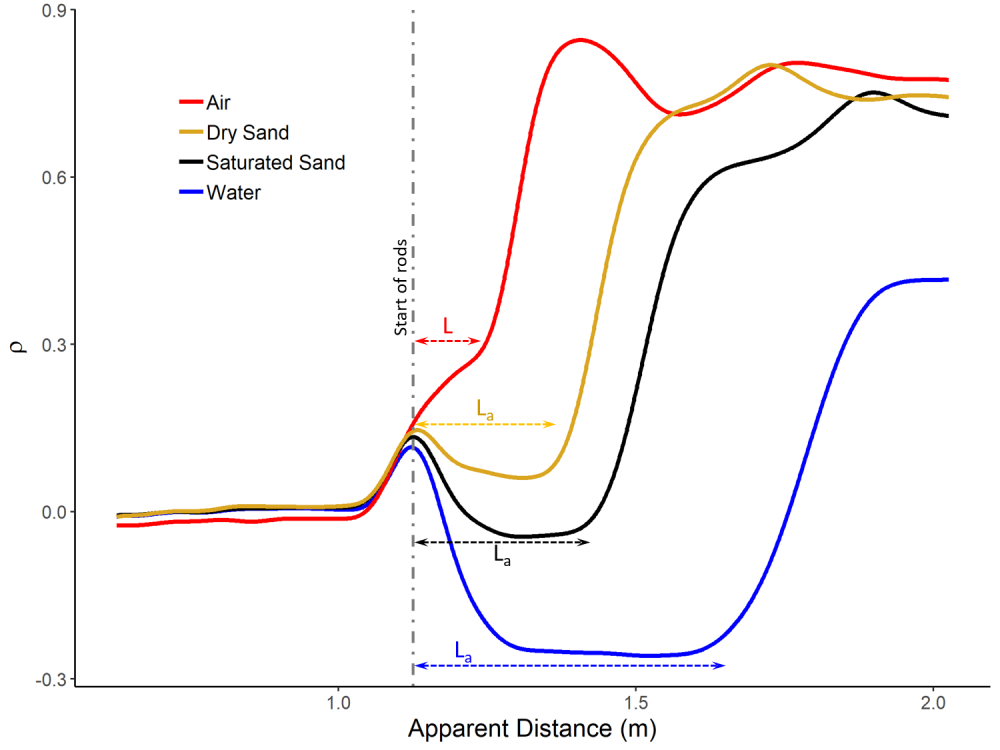
For decades, time-domain reflectometry (TDR) has been one of the leading methods for measuring soil water content. To explain it simply, electromagnetic pulses are sent along rods (or waveguides). Those pulses are reflected at various points along the waveguides—most strongly at the transition from the cable to the waveguides and at the end of the waveguides. The travel time of the pulses is then recorded.
Measurements of the travel time of the pulses are affected by permittivity. Permittivity is the ability to store electrical energy in an electric field. The permittivity of the material surrounding the waveguides has a strong influence on this travel time. Therefore, material with a higher permittivity has a stronger influence on the travel time of the pulses.
The permittivity of water is approximately 80 (depending on temperature), whereas the permittivity of the rest of the soil is generally in the single digits. Consequently, changes in the water content of the soil have the strongest impact on the measurement of the pulse travel time. From these pulses, waveforms are constructed and analyzed, as shown below:

The ratio of the pulse travel time (expressed as a length) to what it would be if the waveguides were surrounded by air is directly related to permittivity:

where Ka is apparent permittivity, L is the true length of the waveguides, and La is the apparent length of the waveguides as estimated by pulse travel time.
Tip: There are a variety of published models that calculate water content from this ratio or permittivity.
Historically, genuine TDR required a complex and expensive system that allowed you to define most, if not all, the parameters. The key parameters include the number of points, the algorithm used to find the start and end points, and any smoothing techniques to reduce noise or variation in the signal. If you require this type of flexibility, our TDR200 Time-Domain Reflectometer offers this option.
The parameters for the SoilVue 10 are all optimized at the factory during calibration to provide a clean, consistent analysis and accurate measure of the true pulse travel time.
Conclusion
The SoilVue 10 TDR Soil Moisture Profile Sensor with TrueWave™TDR technology offers an innovative mechanical design, electronics, and measurement method that address key challenges you may face when making multiple soil moisture profile measurements. To learn more, visit the SoilVue 10 product page or watch the video below.
If you have any questions or comments, post them below.


 Dr. Dirk V. Baker is a Senior Scientist and the Global Science Program Manager at Campbell Scientific. Areas of interest include ecology, agriculture, and meteorology—among others. He has a bachelor's degree in wildlife biology and a doctorate in weed science, both from Colorado State University. Dirk’s graduate and postdoctoral research centered around measuring and modeling wind-driven plant dispersal.
Comments
Please log in or register to comment.