Internal thermistor for optimized measurements


Overview
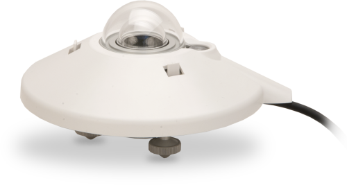
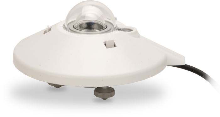
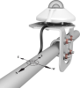
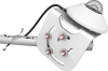
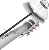
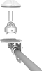
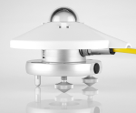
The CMP21, manufactured by Kipp & Zonen, is an ISO Class A (secondary-standard) pyranometer with an internal thermistor. It monitors solar radiation for the full solar spectrum range, and is well-suited for scientific use and in top-level solar-radiation monitoring networks. This pyranometer connects directly to a Campbell Scientific data logger.
Read MoreBenefits and Features
- Includes thermistor for individually optimized temperature compensation
- Compatible with most Campbell Scientific data loggers
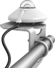
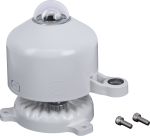
- Integrated bubble level is visible without removing sun shield
- Desiccant-filled drying cartridge prevents dew from forming on the inner sides of the domes
- Compatible with the CVF4 heater/ventilator that keeps the domes free from ice and dew
- Measures reflected solar radiation when inverted
- Provides measurements in direct sunlight, under plant canopies, when the sky is cloudy, and in artificial light
Technical Description
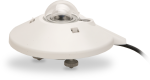
The CMP21 measures solar radiation with a high-quality blackened thermopile protected by two glass domes. An internal thermistor allows individually optimized temperature compensation of the measurements.
The CMP21 has flat spectral sensitivity, from 285 to 2800 nm, that makes it ideal for applications in natural sunlight, under plant canopies, in green houses or buildings, and inverted to measure reflected solar radiation.
A desiccant-filled drying cartridge prevents dew from forming on the inner sides of the CMP21's domes. Campbell Scientific also offers the CVF4 heater/ventilator that keeps its domes free from ice and dew.
The CMP21 includes a white snap-on sun shield that reduces the sensor's temperature. A bubble level and adjusting leveling screws enable the sensor to be leveled without using a leveling base.
Images
Compatibility
Please note: The following shows notable compatibility information. It is not a comprehensive list of all compatible products.
Dataloggers
| Product | Compatible | Note |
|---|---|---|
| CR1000 (retired) | ||
| CR1000X (retired) | ||
| CR300 (retired) | ||
| CR3000 | ||
| CR310 | ||
| CR350 | ||
| CR6 | ||
| CR800 (retired) | ||
| CR850 (retired) |
Additional Compatibility Information
Mounting
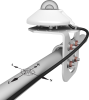
The CMP21 has a bubble level and two leveling feet, which allow it to be leveled without using a leveling base. This pyranometer mounts to a mast, crossarm, or pole (1.0 in. to 2.1 in. OD) via the CM255 or CM255LS mounting stand. The CMP21 should be mounted away from all obstructions and reflective surfaces that might adversely effect the measurement.
Specifications
| Sensor | High-quality blackened thermopile protected by two glass domes |
| Measurement Description | Monitors solar radiation for the full solar spectrum range |
| ISO Classification | Class A (secondary standard) |
| Spectral Range | 285 to 2800 nm |
| Sensitivity | 7 to 14 µV/W/m2 |
| Temperature Dependence of Sensitivity | < 1% (-20° to +50°C) |
| Response Time | < 5 s (95% of final value) |
| Zero Offset Due to Thermal Radiation | < 7 W/m2 (200 W/m2) |
| Non-Stability | < 0.5% (change/year) |
| Non-Linearity | < 0.2% (0 to 1000 W/m2) |
| Directional Error | < 10 W/m2 (up to 80° with 1000 W/m2 beam) |
| Tilt Error | < 0.2% |
| Level Accuracy | 0.1° |
| Impedance | 10 to 100 Ω |
| Operating Temperature Range | -40° to +80°C |
| Typical Signal Output | 0 to 15 mV (for atmospheric applications) |
| Maximum Irradiance | 4000 W/m2 |
| Expected Daily Uncertainty | < 2% |
| Dome Diameter | 5 cm (2 in.) |
| Width | 15 cm (5.9 in.) with shield |
| Height | 9.25 cm (3.64 in.) |
| Weight | 0.9 kg (2 lb) with 10.1 m (33 ft) cable |
FAQs for
Number of FAQs related to CMP21: 6
Expand AllCollapse All
-
A cable length of 300 ft can be used with the understanding that additional noise may be introduced into the measurement. Typically, in systems with pyranometers, the sensors are installed near the data logger (within 50 ft). If an application requires long leads, contact Campbell Scientific for assistance.
-
No. These are all passive devices that create their own voltage signal as a response to the measurement being made. There is, however, a heater and ventilator for these sensors (CVF4) that requires a power supply.
-
Because of the loss of IR radiation, nearly all thermopile instruments typically have a negative offset. This offset is most easily visible at night-time, when a small negative value is read instead of zero. This same offset is present during the daytime, but it is not as visible because of the large solar signal.
Another common issue involves leveling an instrument. Leveling a thermopile instrument can cause errors in the direct beam component because the cosine response is not correct. These errors are more notable when the sun is close to the horizon because the angle is so shallow.
-
The ISO and WMO classify First Class pyranometers, such as the CMP6-L, as suitable for network operations. However, if accuracy is of paramount concern, consider using Class A pyranometers, such as the CMP11-L and CMP21, instead.
-
All of these pyranometers measure the amount of solar short-wave radiation incident on a surface. Because of their accuracy and performance level, the CMP11 and CMP21 are classified by the International Organization for Standardization (ISO) and World Meteorological Organization (WMO) as Secondary Standard sensors, representing the highest level of measurements made by pyranometers. In comparison, the CMP6 is classified as a First Class sensor, which is the middle classification for pyranometers. (Second Class is the lowest pyranometer classification.)
-
Yes. Each pyranometer is shipped with an instruction manual provided by Kipp & Zonen that contains information concerning its construction, spectral sensitivity, cosine response, and a simple sensor check out procedure. Included with the sensor and manual is a calibration certificate with the sensor sensitivity value and serial number.
Privacy Policy Update
We've updated our privacy policy. Learn More
Cookie Consent
Update your cookie preferences. Update Cookie Preferences